MIDI and Audio

G2 MIDI Controller

I own a Nord G2 Engine, and while it's a great synth, it lacks all of the user interface coolness of the G2 or G2X keyboards. There's no way to select a patch except blindly using bank/program select from another synth, or by having a computer tied to it to display the patch listings.

I've overcome this problem by building a AVR-based MIDI controller that can get patch names from the G2 with MIDI, display a patch name on the screen, and let you load it into a slot on the G2.

The Finished Prototype

This is the front panel. The LCD panel displays patch numbers and names, The knob is an endless rotary encoder used to dial up a patch, the keypad allows a number to be typed in directly, and the buttons on the right control mode, patch loading etc. LEDs display communication status with the G2, MIDI busy, and so on. Current features:

  • Query current patch by slot
  • Dial/Enter patch number, buttons to switch banks
  • Query name of patch by bank/number
  • Load patch into synth

Electronics

These are the major components in the controller:

Prototyping with solder is a bit of a pain. I've got an AVR dev board that I made up for experimenting with an Atmel AT90S4433. The AtMega8L chips I'm using now a pin compatible and can be dropped straight into the dev board with no problems.

The dev board is the small PCB in the middle of the breadboard, it just provides power and crystal + caps, and then breaks out programmer and all available data pins to be plugged into circuits around the board. I use ribbon cable and machined IC pin sockets so the broken out pins can be easily plugged into the breadboard.

This board has an LCD module and keypad installed, there's a shift register for the LCD in the lower left, keypad circuits in the lower right, and the MIDI in and out circuits in the top right. I had originally played with 4 and 8-bit parallel interfaces for the LCD, but 4-bit mode was a pain, and 8 bits ate too many pins. The shift register is surprisingly easy to get working.

Front Panel: showing the LCD module, keypad, LED banks, rotary encoder, and the four extra buttons, all with the ribbon cables that link them to the main board.

The front panel is currently held together with hot-melt glue. This will be replaced with a sensible epoxy as soon as I'm convinced that nothing else needs to be added.

Front and back of the circuit board. This is a prototyping board available off the shelf. I didn't have the patience to route a double sided board for the first boxed prototype.

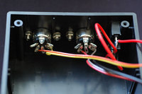
MIDI In/Out Circuits: There's nothing complicated about building MIDI circuits. There are lots of schematics available around the place. You need an optoisolator for the input side, and 6n139 and 6n138 parts both seem to work. Output side should be buffered but in this case it's hooked up directly to the AVR TX pin with a couple of 220-ohm resistors to avoid deadly shorts.

The AVR UART handles MIDI just fine. I recommend some sort of slow buffer for MIDI out and using the serial interrupt stuff for incoming MIDI. Particularly if you're using an 8MHz crystal, you've got plenty of

Power Circuit: It's a board that runs of DC 5V. To give a little flexibility, I added a diode rectifier and a 78L05 regulator. The 78L05 gets a little warm, so I should probably replace it with something with a heatsink. If I added some caps to this, it would be able to run from AC as well.

Construction

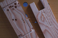
Building kits into the sort of thermo plastic hobby box makes things easier, but the finish isn't great. For a first prototype, it's fine. Drilling large holes in the front of this plastic can cause the plastic to split and crack so I made up a wood jig out of pine, and used a dremel to cut slots so the lid fitted into it firmly. The fork-shaped piece of wood is clamped to the top for support when drilling between the tines.
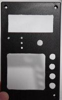
Empty front panel MIDI plugs and power Jig for drilling front panel


© Bruce Murphy, 2006.
Email